Item Description
Large Torque 120MM Flange Output Spur Gear Planetary Velocity Reducer
Planetary gearbox is a kind of reducer with wide flexibility. The inner equipment adopts reduced carbon alloy metal carburizing quenching and grinding or nitriding approach. Planetary gearbox has the characteristics of tiny structure dimension, large output torque, large speed ratio, large efficiency, risk-free and dependable overall performance, etc. The interior gear of the planetary gearbox can be divided into spur equipment and helical gear. Consumers can pick the proper precision reducer in accordance to the needs of the application.
Product Description
Description:
(1).The output shaft is manufactured of huge measurement,big span double bearing design and style,output shaft and planetary arm bracket as a whole.The input shaft is placed straight on the world arm bracket to guarantee that the reducer has large running accuracy and greatest torsional rigidity.
(2).Shell and the interior ring equipment employed integrated layout,quenching and tempering following the processing of the tooth so that it can obtain large torque,large precision,high put on resistance.In addition area nickel-plated anti-rust treatment method,so that its corrosion resistance significantly increased.
(3).The planetary equipment transmission employs total needle roller with out retainer to boost the make contact with surface,which greatly updates structural rigidity and service life.
(4).The equipment is made of Japanese imported materials.Soon after the metallic reducing approach,the vacuum carburizing warmth therapy to fifty eight-62HRC. And then by the hobbing,Get the very best tooth condition,tooth direction,to guarantee that the gear of substantial precision and excellent impact toughness.
(5).Input shaft and sunshine equipment integrated construction,in order to boost the operation accuracy of the reducer.
Characteristics:
1.With bevel equipment reversing mechanism,appropriate angle steering output is understood.
2.Spherical flange output.threaded link,standardized size.
three.The input relationship technical specs are complete and there are man selections.
4.Straight tooth transmission,single cantilever composition, basic design and style and high expense efficiency.
five.Keyway can be opened in the force shaft.
6.Lower return backlash,high precision,higher overall performance,high rifidity.
seven.Space-conserving layout:right angle reducer utilizing spiral bevel equipment,the motor can be installed to achieve ninety diploma bending,saving set up area.
eight.Velocity ratio selection:3-100
nine.Measurement assortment:sixty-120mm
ten.Precision selection:8-16arcmin
| Specifications | PVLN60 | PVLN90 | PVLN120 | |||
| Technal Parameters | ||||||
| Max. Torque | Nm | 1.5times rated torque | ||||
| Emergency End Torque | Nm | 2.5times rated torque | ||||
| Max. Radial Load | N | 240 | 450 | 1240 | ||
| Max. Axial Load | N | 220 | 430 | 1000 | ||
| Torsional Rigidity | Nm/arcmin | 1.eight | four.85 | 11 | ||
| Max.Input Velocity | rpm | 8000 | 6000 | 6000 | ||
| Rated Enter Speed | rpm | 4000 | 3500 | 3500 | ||
| Noise | dB | ≤58 | ≤60 | ≤65 | ||
| Average Lifestyle Time | h | 20000 | ||||
| Efficiency Of Full Load | % | L1≥95% L2≥92% | ||||
| Return Backlash | P1 | L1 | arcmin | ≤8 | ≤8 | ≤8 |
| L2 | arcmin | ≤12 | ≤12 | ≤12 | ||
| P2 | L1 | arcmin | ≤16 | ≤16 | ≤16 | |
| L2 | arcmin | ≤20 | ≤20 | ≤20 | ||
| Second Of Inertia Table | L1 | three | Kg*cm2 | .forty six | one.73 | 12.seventy eight |
| four | Kg*cm2 | .forty six | 1.seventy three | 12.seventy eight | ||
| five | Kg*cm2 | .forty six | one.73 | 12.seventy eight | ||
| seven | Kg*cm2 | .forty one | one.forty two | 11.38 | ||
| 10 | Kg*cm2 | .forty one | one.42 | 11.38 | ||
| L2 | twelve | Kg*cm2 | .44 | 1.49 | twelve.eighteen | |
| fifteen | Kg*cm2 | .forty four | 1.49 | 12.eighteen | ||
| 16 | Kg*cm2 | .72 | 1.forty nine | twelve.eighteen | ||
| 20 | Kg*cm2 | .44 | one.forty nine | twelve.eighteen | ||
| 25 | Kg*cm2 | .forty four | one.49 | twelve.18 | ||
| 28 | Kg*cm2 | .forty four | one.forty nine | 12.eighteen | ||
| thirty | Kg*cm2 | .44 | 1.49 | 12.eighteen | ||
| 35 | Kg*cm2 | .forty four | 1.49 | twelve.eighteen | ||
| 40 | Kg*cm2 | .forty four | 1.forty nine | 12.18 | ||
| fifty | Kg*cm2 | .34 | one.twenty five | 11.forty eight | ||
| 70 | Kg*cm2 | .34 | 1.twenty five | eleven.forty eight | ||
| 100 | Kg*cm2 | .34 | one.25 | eleven.forty eight | ||
| Technical Parameter | Degree | Ratio | PVLN60 | PVLN90 | PVLN120 | |
| Rated Torque | L1 | three | Nm | 27 | 96 | 161 |
| four | Nm | 40 | 122 | 210 | ||
| five | Nm | 40 | 122 | 210 | ||
| 7 | Nm | 34 | ninety five | one hundred seventy | ||
| ten | Nm | 16 | fifty six | 86 | ||
| L2 | 12 | Nm | 27 | ninety six | 161 | |
| 15 | Nm | 27 | 96 | 161 | ||
| sixteen | Nm | forty | 122 | 210 | ||
| 20 | Nm | forty | 122 | 210 | ||
| 25 | Nm | 40 | 122 | 210 | ||
| 28 | Nm | 40 | 122 | 210 | ||
| thirty | Nm | 27 | ninety six | 161 | ||
| 35 | Nm | forty | 122 | 210 | ||
| 40 | Nm | forty | 122 | 210 | ||
| 50 | Nm | forty | 122 | 210 | ||
| 70 | Nm | 34 | ninety five | one hundred seventy | ||
| 100 | Nm | 16 | 56 | 86 | ||
| Degree Of Defense | IP65 | |||||
| Operation Temprature | ºC | – 10ºC to -90ºC | ||||
| Weight | L1 | kg | one.7 | four.four | twelve | |
| L2 | kg | 1.9 | five | 14 | ||
Organization Profile
Packaging & Shipping and delivery
1. Direct time: 7-10 working days as usual, twenty working times in hectic season, it will be dependent on the detailed buy quantity
two. Supply: DHL/ UPS/ FEDEX/ EMS/ TNT
| Application: | Motor, Motorcycle, Machinery, Marine, Agricultural Machinery, Textile Machinery |
|---|---|
| Function: | Change Drive Direction, Speed Changing, Speed Reduction |
| Layout: | Coaxial |
| Hardness: | Hardened Tooth Surface |
| Installation: | Vertical Type |
| Step: | Single-Step |
###
| Samples: |
US$ 399/Piece
1 Piece(Min.Order) |
|---|
###
| Customization: |
|---|
###
| Specifications | PVLN60 | PVLN90 | PVLN120 | |||
| Technal Parameters | ||||||
| Max. Torque | Nm | 1.5times rated torque | ||||
| Emergency Stop Torque | Nm | 2.5times rated torque | ||||
| Max. Radial Load | N | 240 | 450 | 1240 | ||
| Max. Axial Load | N | 220 | 430 | 1000 | ||
| Torsional Rigidity | Nm/arcmin | 1.8 | 4.85 | 11 | ||
| Max.Input Speed | rpm | 8000 | 6000 | 6000 | ||
| Rated Input Speed | rpm | 4000 | 3500 | 3500 | ||
| Noise | dB | ≤58 | ≤60 | ≤65 | ||
| Average Life Time | h | 20000 | ||||
| Efficiency Of Full Load | % | L1≥95% L2≥92% | ||||
| Return Backlash | P1 | L1 | arcmin | ≤8 | ≤8 | ≤8 |
| L2 | arcmin | ≤12 | ≤12 | ≤12 | ||
| P2 | L1 | arcmin | ≤16 | ≤16 | ≤16 | |
| L2 | arcmin | ≤20 | ≤20 | ≤20 | ||
| Moment Of Inertia Table | L1 | 3 | Kg*cm2 | 0.46 | 1.73 | 12.78 |
| 4 | Kg*cm2 | 0.46 | 1.73 | 12.78 | ||
| 5 | Kg*cm2 | 0.46 | 1.73 | 12.78 | ||
| 7 | Kg*cm2 | 0.41 | 1.42 | 11.38 | ||
| 10 | Kg*cm2 | 0.41 | 1.42 | 11.38 | ||
| L2 | 12 | Kg*cm2 | 0.44 | 1.49 | 12.18 | |
| 15 | Kg*cm2 | 0.44 | 1.49 | 12.18 | ||
| 16 | Kg*cm2 | 0.72 | 1.49 | 12.18 | ||
| 20 | Kg*cm2 | 0.44 | 1.49 | 12.18 | ||
| 25 | Kg*cm2 | 0.44 | 1.49 | 12.18 | ||
| 28 | Kg*cm2 | 0.44 | 1.49 | 12.18 | ||
| 30 | Kg*cm2 | 0.44 | 1.49 | 12.18 | ||
| 35 | Kg*cm2 | 0.44 | 1.49 | 12.18 | ||
| 40 | Kg*cm2 | 0.44 | 1.49 | 12.18 | ||
| 50 | Kg*cm2 | 0.34 | 1.25 | 11.48 | ||
| 70 | Kg*cm2 | 0.34 | 1.25 | 11.48 | ||
| 100 | Kg*cm2 | 0.34 | 1.25 | 11.48 | ||
| Technical Parameter | Level | Ratio | PVLN60 | PVLN90 | PVLN120 | |
| Rated Torque | L1 | 3 | Nm | 27 | 96 | 161 |
| 4 | Nm | 40 | 122 | 210 | ||
| 5 | Nm | 40 | 122 | 210 | ||
| 7 | Nm | 34 | 95 | 170 | ||
| 10 | Nm | 16 | 56 | 86 | ||
| L2 | 12 | Nm | 27 | 96 | 161 | |
| 15 | Nm | 27 | 96 | 161 | ||
| 16 | Nm | 40 | 122 | 210 | ||
| 20 | Nm | 40 | 122 | 210 | ||
| 25 | Nm | 40 | 122 | 210 | ||
| 28 | Nm | 40 | 122 | 210 | ||
| 30 | Nm | 27 | 96 | 161 | ||
| 35 | Nm | 40 | 122 | 210 | ||
| 40 | Nm | 40 | 122 | 210 | ||
| 50 | Nm | 40 | 122 | 210 | ||
| 70 | Nm | 34 | 95 | 170 | ||
| 100 | Nm | 16 | 56 | 86 | ||
| Degree Of Protection | IP65 | |||||
| Operation Temprature | ºC | – 10ºC to -90ºC | ||||
| Weight | L1 | kg | 1.7 | 4.4 | 12 | |
| L2 | kg | 1.9 | 5 | 14 | ||
Benefits of a Planetary Gearbox With Output Shaft
The output shaft of a Planetary Gearbox connects to the driven wheels, while the input shaft comes from the engine. These gears are interlinked and create a wide range of gear reductions, which are necessary to get a vehicle rolling comfortably. Gear reductions are the place where the various “gears” are located. Here are some examples. They can help you determine what you need for your vehicle. You might also want to learn about planetary gears.
Planetary gearboxes
Modern cars are most likely equipped with planetary gearboxes. If you’re unsure if your vehicle uses planetary gears, you should first consult your car’s owner’s manual. If not, contact your dealership’s service department for more information. Otherwise, you can do a quick search on the internet to find out whether your car has a planetary gearbox. These gearboxes are generally more complex than ordinary gears. Additionally, they are equipped with more parts and require lubrication.
In addition to their low noise levels, planetary gearboxes are also remarkably efficient at transmission. These features make them ideal for applications requiring high torque and small footprints. Unfortunately, there are many different types of planetary gearboxes on the market, making it difficult to find the right one. The following article will give you some guidelines to help you choose the right planetary gearbox for your needs. Let’s take a look!
Planetary gears
A planetary gearbox has two main components: the sun gear (also known as the central or input) and the planet gears (also known as outer or peripheral). These gears are connected together by a carrier to the output shaft of the machine. In some applications, it is necessary to use a planetary gearbox with lubrication to prevent wear and tear. A planetary gearbox also has a small ring gear that helps hold the planet gears together.
The main advantage of a planetary gearbox is that it uses several teeth that engage at once, allowing for high-speed reduction with a small number of gears. Because the gears are relatively small, they have lower inertia than their larger counterparts. Planetary gearboxes are compact, which makes them popular for space-constrained applications. Because of their compact size and efficiency, planetary gearboxes are also commonly used in motor vehicles.
Planetary gearboxes with output shaft
For high-speed, dynamic applications, planetary gearbox units with output shaft provide the optimal solution. Thanks to their low inertia, these gearheads deliver superior performance in many industrial applications. Additionally, their wide range of variants allows users to select the perfect product for their application. This article examines some of the key benefits of planetary gearboxes with output shaft. Read on to learn more.
The planetary gearbox has two major components: a sun gear and planet gears. The sun gear is usually the input gear, while the planet gears are located at the outer edges of the system casing. Planet gears are held together by a carrier that is connected to the output shaft. Before choosing a particular gearbox for your application, make sure that you check the specific requirements and the environment to which the unit will be subjected.
A planetary gearbox has less stages of gears, and thus lower backlash compared to spur gearboxes. Backlash is lost motion that occurs when the teeth of the gears are out of perfect alignment. This problem is common in all gears, but is significantly less in planetary gearboxes. As such, planetary gearboxes are more efficient. They can also be customized according to the specific engine model and motor flange.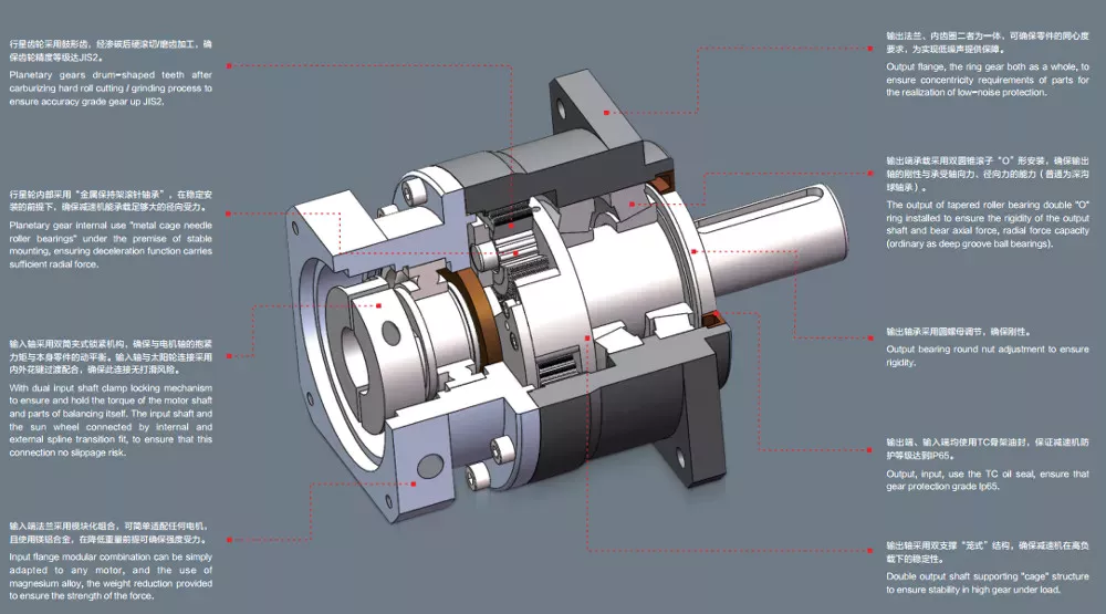
Planetary gearboxes with carrier
A planetary gearbox is a type of gearbox with three or more stages. They have a sun gear, which is usually the input gear, and planet gears, also called the outer gears. The carrier that connects the planet gears to the output shaft is called a ring gear. A planetary gearbox is generally designed to meet specific application and environmental requirements, but there are some factors to consider when choosing one.
The compact footprint of planetary gear sets results in high heat dissipation. This can be a problem in applications with sustained performance or high speeds. As a result, planetary gear sets often include lubricants, which present a cooling effect while also reducing noise and vibration. Some planetary gears even feature a carrier to make the installation process easier. Here are some things to keep in mind when choosing a planetary gear set.
Planetary gearboxes with carrier have several advantages over other types of gearboxes. Unlike conventional gearboxes, planetary gears have a common central shaft, and the tangential forces between the gears cancel out at the center of the ring gear. Because of this, planetary gearboxes are commonly used in input/output applications, and their compact size allows for a wide range of gear reductions. These gears can also produce higher torque density.
Planetary gearboxes with traction
Planetary gears are similar to the planetary system, in that each pinion rotates around a sun gear. The output of the planetary gear unit is lower than the drive rotation speed, but the torque is higher. As the number of planet gear wheels increases, so does the torque. Planetary gear systems contain three to four planet gears, and each is in constant mesh with the others. Power applied to any one member rotates the entire assembly.
Typical applications for planetary gear sets include high-precision motion control. In these applications, high torque, torsional stiffness, and low backlash are required. Planetary gear sets are also ideal for motors with higher speeds. A number of factors contribute to the reliability of these devices. The low backlash and large torque capacity of a planetary gear motor allow them to be used in a wide range of applications.
Planetary gearboxes with electric motors
If you’re in the market for a new gearbox, you may have already heard about planetary gearboxes. The planetary gearbox is a high-efficiency, low-noise gearbox. CZPT manufactures high-torque planetary gearboxes with low backlash. They also make economy planetary gearboxes for lower loads. However, with so many different types available, choosing the right one for your needs can be challenging.
These planetary gearboxes are a compact alternative to conventional pinion-and-gear reducers. They offer high-speed reduction and high torque transfer, and are often used for space-constrained applications. But before you can understand how they work, you’ll need to understand a little about their construction. There are a few things to look for that you may not have noticed before.
The most common type of planetary gearbox is a PM81/LN. It features a set of DC brush motors with diameter 77mm, a stator, and two or more outer gears. Each of these gears is connected to an output shaft through a carrier. They can also be used with brakes, encoders, or a clutch. A planetary gearbox is one of the most reliable gearbox types on the market.
Planetary gearboxes with hydraulic motors
A planetary gearbox is a combination of two gears, the sun and the planets. The sun gear rotates at high speed, while the planets roll around and orbit around the ring gear. The output shaft has the same direction of rotation as the input shaft. The benefits of a planetary gearbox include high reduction ratios, efficiency, space-saving compactness, and higher overload capacity. These gears are also more stable and compact, and they do not suffer from self-locking properties.
Planetary gearboxes are a highly efficient way to power hydraulic lifts. They can be input via electric, hydraulic, or air motors. The drive arrangement can be mounted on a bare shaft, splined shaft, or a parallel keyed input shaft. Depending on the application, bespoke gearboxes can be manufactured with a variety of features and functions.
Planetary gearboxes with combustion engines
There are many different applications of planetary gear sets. The most common is the distribution of power between two wheels in a car’s drive axle. Four-wheel drives use two axle differentials, which are further augmented by a centre differential. Hybrid electric vehicles use summation gearboxes to distribute power from the combustion engine to the wheels and to an electric motor. Planetary gear sets also combine the two different types of motors to form one hybrid vehicle.
To understand how planetary gear sets work, it is important to understand the underlying mechanical principles. For example, Fig. 4.6 shows a stick diagram illustrating two planetary gear sets connected by a lever. The two levers are the same length, so the system is analogous to a single lever. When calculating the torque, it is essential to consider the lever diagram. Similarly, if two gear sets are connected by vertical links, the horizontal links must be horizontal.


editor by CX 2023-03-28


